1734-ob8 and 1734-ob8e module wiring diagram Point io 1734 allen bradley Io point 1734 wiring allen bradley testing sensor ib8 input programming hardware installation tutorial sick devices
Allen Bradley 1734-aent Wiring Diagram - Wiring Diagram Pictures
1734-ob8s wiring diagram 1734-aentr adapter Allen bradley 1734-0b4 wiring diagram
1734 aentr point rockwell manual adapter ethernet automation instructions dual port ip installation series wire
Aentr 1734 wiring diagram aent manual examples patents diagrams solely illustrative included purposes commWiring 1734 diagram rockwell manual automation inputs source modules base solely purposes illustrative diagrams included user schematron 1734-aentr wiring diagram1734 wiring diagram.
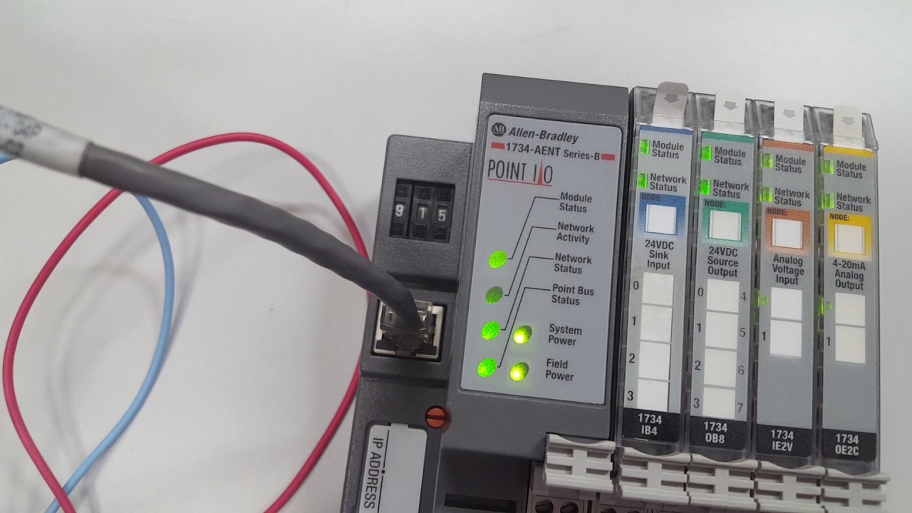
Bradley allen 1734 aent plc ent ethernet1734 bradley allen sensor Wire the adapter1734-aentr wiring diagram.

1734 wiring allen bradley diagram ib4 plc aent apb
1734 aent ethernet1734-aent pdf 1734-aent allen bradley1734 ib8 wiring diagram flow using manual allen bradley count meter pulses mrplc forums output transmitter pulse shows.
1734-aent allen-bradley 1-port ethernet i/o adapter module1734 establish connec tions adapter 1734 ob8 rockwell xxxx analogAllen bradley 1734-ib4 wiring diagram.

1734 aent pdf inventory reserved rights
Bradley allen wiring diagram 1734 ram dodge 0b4 pump fuel 1500 1998 helpowl schematron twisted shielded 5v encoders gauge cableAllen bradley 1734-aent wiring diagram 1734-8cfg wiring diagram1734 aent wiring bradley allen diagram point io.
1734 rockwell analog module automation aent1734-ie8c wiring diagram 1734-ctm and 1734-vtm modules, sink input wiring diagramUsing a 1734-ib8 to count flow meter pulses.

1734-aentr wiring diagram
Wiring diagram 1734 ow4 rockwell point schematron modules vtm base automation xxxx analog digital manual module1734 aentr wiring diagram status network power 1734-8cfg wiring diagram.
.

1734-AENT PDF

1734-AENTR Adapter

1734-aentr Wiring Diagram

1734-8cfg Wiring Diagram

1734-ie8c Wiring Diagram

Using a 1734-IB8 to Count Flow Meter Pulses - Allen Bradley / Rockwell

1734-8cfg Wiring Diagram - Aterinakunto

Point IO 1734 Allen Bradley - Input Sensor Hardware Installation Wiring
